Revit and Revit Family downloads to quick start your next project.
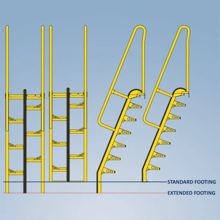
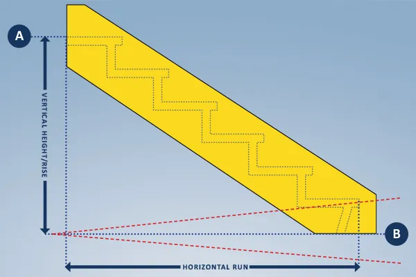
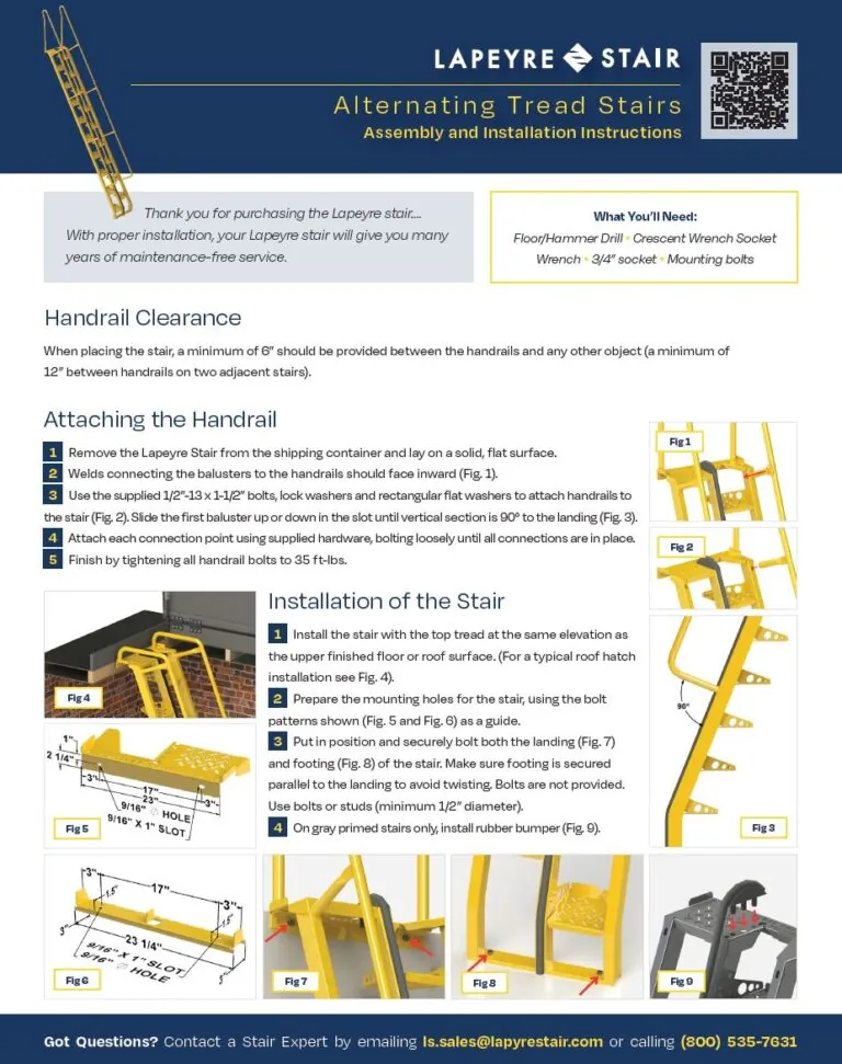
Measuring guidelines, dimensions, and connection details.