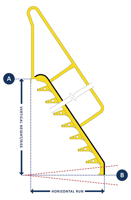
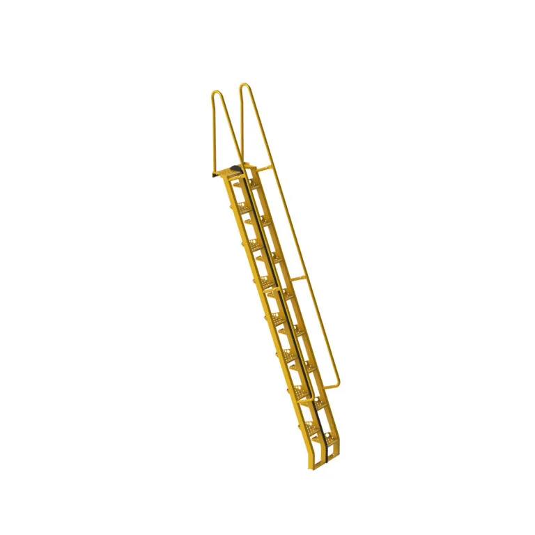
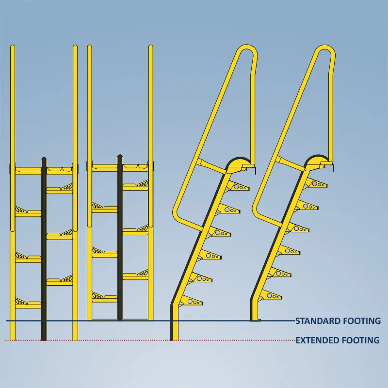
Alternating tread stairs are built to exact, vertical height measured from (A) where the top landing of the stair attaches to the upper, finished floor to (B) the lower, finished floor where the foot of the stair will be secured.
Sloped Floors
If the finished floor is not level, the slope will impact the vertical height of the stair. One way to accurately measure vertical height on sloped floors is by using a string/line level.
Use the horizontal projections chart on the right to determine the approximate location of the foot of the stair based on the stair angle and estimated height.
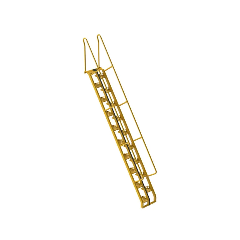
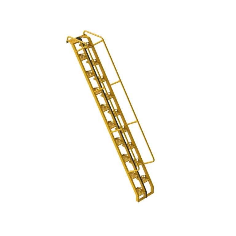
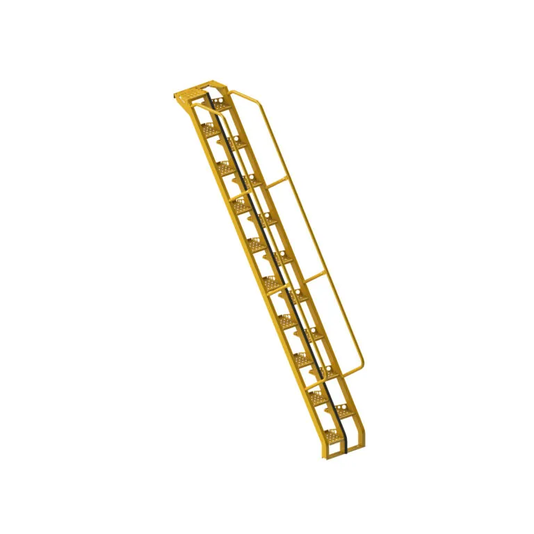
Alternating tread stairs used for roof hatch access
Special guidelines apply when measuring for alternating tread stairs that will be used to access a roof hatch.
OSHA and IBC require stairs to have minimum head/vertical clearance of 80 inches. These requirements are based on the slope of standard stairs. Due to the steeper angle of alternating tread stairs, we recommend a minimum head clearance of 88.2 inches for 56° alternating tread stairs and 108.7 inches for 68° alternating tread stairs.
HEAD CLEARANCE FOR 56° ALTERNATING TREAD STAIRS
HEAD CLEARANCE FOR 68° ALTERNATING TREAD STAIRS
Alternating Tread Stair Horizontal Projections
VERTICAL HEIGHT/RISE
HORIZONTAL RUN
STEEL, 56°
STEEL, 68°
ALUMINUM, 68°
24"
N/A
N/A
15.96”
30"
N/A
N/A
18.59”
36"
28.93”
N/A
20.41”
42"
33.11”
23.08”
23.08”
48"
37.25”
25.66”
25.66”
54"
41.37”
28.2”
28.2”
60"
44.91”
30.28”
30.71”
66"
49.07”
32.83”
33.2”
72"
53.21”
35.36”
35.36”
78"
57.33”
37.86”
37.86”
84"
61.44”
40.04”
40.35”
90"
65.15”
42.56”
42.56”
96"
69.27”
45.05”
45.05”
102"
73.39”
47.28”
47.54”
108"
77.49”
49.78”
50.02”
114"
81.59”
52.27”
52.27”
120"
85.38”
54.75”
54.75”
126"
89.49”
57.01”
57.23”
132"
93.59”
59.5”
59.69”
138"
97.68”
61.98”
61.98”
144"
101.77”
64.45”
64.45”
150"
105.62”
66.74”
66.91”
156"
109.71”
69.21”
69.38”
162"
113.8”
71.68”
71.68”
168"
117.89”
73.98”
74.14”
174"
121.97”
76.45”
76.61”
180"
125.85”
78.92”
78.92”
186"
129.94”
81.38”
81.38”
192"
134.02”
83.7”
83.3”
198"
138.11”
86.16”
86.3”
204"
142.19”
88.62”
88.62”
210"
146.09”
91.08”
91.08”
216"
150.17”
93.41”
93.54”
222"
154.25”
95.87”
N/A
228"
158.33”
98.33”
N/A
234"
162.4”
100.78”
N/A
240"
166.32”
103.12”
N/A
Alternating Tread Stair Standard Dimensions
56° STEEL
68° STEEL
68° ALUMINUM
Minimum floor-to-floor height
36"
42"
24"
Maximum floor-to-floor height
240"
240"
216"
Overall height, standard handrails
Height + 42"
Height + 42"
Height + 42"
Overall height, optional handrails
Height + 5¾"
Height + 5¾"
Height + 3¾"
Overall width
23"
23"
23"
Recommended minimum floor opening, width
35"
35"
35"
Recommended maximum floor opening, length
70" + ⅔ floor thickness
62" + ⅖ floor thickness
62" + ⅖ floor thickness
Minimum riser height
6.417"
7.517"
7.175"
Maximum riser height
7.7"
9.02"
9.566"
Additional Dimensions and Pricing
View overall height, horizontal run, weight, and pricing by type of alternating tread stair:
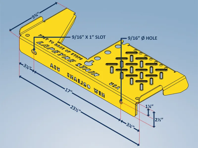
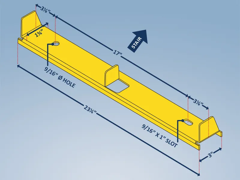
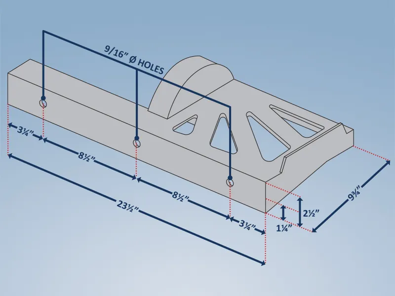
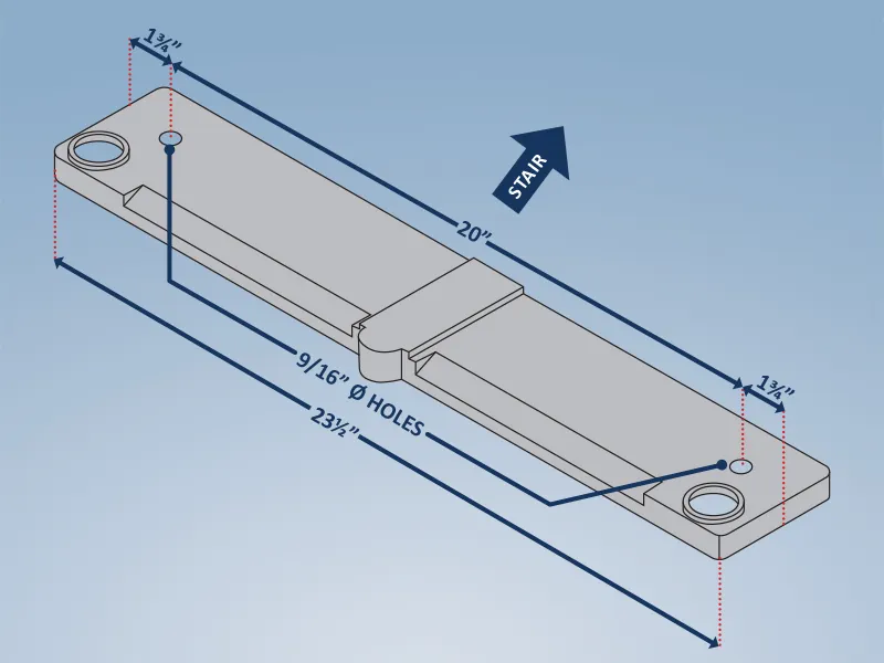
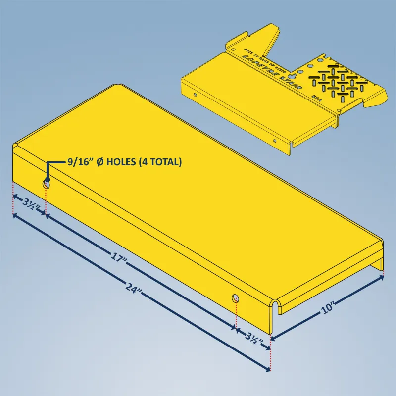
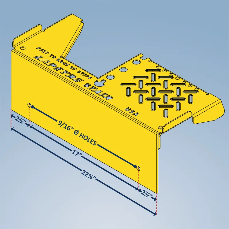
Alternating Tread Stair Standard Connection Details
The top tread/landing and the bottom footing of an alternating tread stair bolt into place using customer-supplied bolts or studs with a minimum 1/2″ diameter. The drawings below illustrate the standard bolt patterns for steel and aluminum alternating tread stairs.
TOP TREAD/LANDING BOLT PATTERN, STEEL ALTERNATING TREAD STAIRS
Options For Alternating Tread Stair Installations That Requires Special Connections
Micro Platform
Bolts to the top landing/platform of the stair to add an additional 10″ to the length. Customer-supplied struts are required when using a micro platform.